
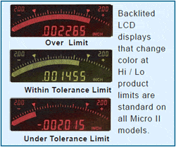
 Micro IIi Readouts incorporate backlit LCD displays that flag out-of-tolerance conditions by changing color from green to red. Seven decade digital displays show actual feature sizes or deviations from nominal sizes. They also include analog bargraphs to graphically display the test piece condition relative to the product limits. Auto-Zero and Auto-span setting features make these instruments very operator friendly. USB & RS-232C serial data and process control outputs are standard.
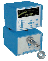
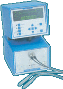
Micro IIi model AEQ 42-11-60 with single master type air probe and master ring provides fast and accurate inspection of internal diameters.
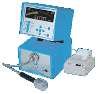 RS-232 serial data ports are standard on all Micro IIi‘s. Model AEQ 42-11-10 with Air probe connected to Mini-Printer model IMP- 24 via the RS-232 port is shown at the right.
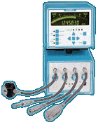 Multiple inputs with single display — Auto-select models direct multiple inputs to a single display. As gages are sequentially inserted in the workpiece, the readout automatically senses the active gaging member and displays the reading. Up to four air gages or pairs of LVDT inputs can be connected to a single display. Micro IIi model AEQ 42-14A- 60 is shown at the to the right.
 LVDT Readouts — Factory installed interface modules provide the capability to operate LVDT type inductive probes. (See inductive probes on pages 34 &35). Model AEQ 42-11-E2 is shown at the left.
Multi-Channel Micro IIi Readouts
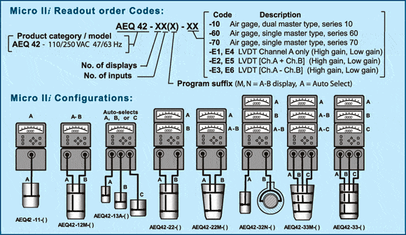
Multi-channel Micro IIi readouts come with up to four input channels which can be configured for operation with either dimensional air gages or LVDT electronic gaging cartridges.
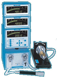
Model AEQ-42-32N-60 connected to an Air probe and Air ring gage with Guide Chute is shown above. See Guide chutes on page 23.
Dual Input Micro IIi models with three displays provide fast, accurate inspection of the internal and external diameters of mating parts. The upper display shows the I.D. size, the middle display shows O.D. size, and the lower display shows the calculated clearance between the parts.
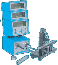
Model AEQ-42-32N-60-E2 with air probe and Vee gage incorporating inductive probes. See page 34 for more on Vee gages with guide chutes.
Taper Gaging applications using Micro IIi Readouts — see page 28
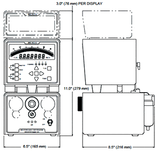
Micro IIi Readout Technical Data
Digital display
Red-green backlited, 7 decade, LCD shows actual part sizes. Digital resolutions are set according to the Hi & Lo product limit span — see table at bottom of page.
Bargraph display
Red-green backlited, 81 segment bargraph, graphically displays the workpiece size and acceptance limits.
Out-of-tolerance Indicators
O/T conditions are flagged by changing the displays from green to red.
Auto-Zero feature (single master)
Micro IIi readouts configured for single master operation have their sensitivities set at the factory using master standards. These instruments are zeroed by the user placing a setting master on the gage and pressing the center key to Auto-Zero the readout.
Auto-Span feature (dual master)
Users set the sensitivity, and zero on Micro IIi readouts configured for dual master operation using Min & Max setting masters. Pressing the center key starts the Auto-Span setting cycle with prompts for the user to sequentially place the setting masters on the gaging member; the sensitivity and zero are then set automatically.
Features, front panel:
Gage 1X — Sets Hi/Lo limits at 50% of full scale.
Gage 2X — Sets Hi/Lo limits at 25% of full scale.
Hi/Lo — Inputs product acceptance limits.
Master — Inputs master sizes.
Print button — Transmits serial data output.
T.I.R. mode button — Activates T.I.R. mode on single channel readouts, indexes active channel on multi-channel readouts.
Arrow key array — Navigates set-up data, and activates Auto-Zero & Auto-Calibration cycles.
Pneumatic Zero adjust (On air gage modules only)
Air Status indicator — indicates correct air pressure.
Gage inputs, specify from 1 to 4 input modules per enclosure:
Air gage, series 10 — all dual master types.
Air gage, series 60,70 or 80 — single master types:
LVDT Input, high gain — ranges < .0015″ (.038mm)
LVDT Input, low gain — gaging ranges > .00075″ (.019mm)
Features, rear panel:
Polarity of input channels (Slide switch).
Inch or metric unit selection (Slide switch).
Printer configuration (Slide switch).
Operator front panel lockout (Slide switch).
Outputs, rear panel:
Digital — RS-232C serial port (9 pin Sub-D male) outputs digital display readings.
I/O Process control — (9 pin Sub-D female)
Commands print data,T.I.R. mode; outputs:
over/under tolerance conditions (TTL 2 ma. max.).
Power required: (Not field selectable)
110/250 VAC 47 – 63 Hz (Order code -42)
Weight: Single channel unit: – 12 Lbs (5.5 Kg)
+ 2 Lbs (.9 Kg) / additional channel
Air gage module requirements:
.5 to 2 SCFM @ 40 to 150 psi (The actual air flow
depends on nozzle sizes and gaging ranges of the
air gage members connected to the readout).
Digital Display Resolutions (default settings)
| Min-max range | Digital Resolution |
| less than.00021″ (.0053 mm) | .000002″ (.00005 mm) |
| less than .0011″ (.028 mm) | .000005″ (.0001 mm) |
| less than .0021″ (.053 mm) | .00001″ (.0005 mm) |
| less than .0301″ (.765 mm) | .00005″ (.001 mm) |