
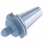
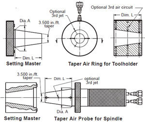
Tapers. 3.5 in / ft. with or
without flange contact.
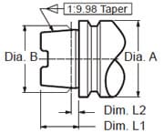
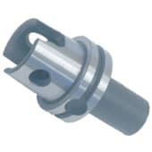 I.S.O HSK 1:9.98 taper ratio
and Kennametal KM Tapers
with flange contacts.
self-holding Tapers.
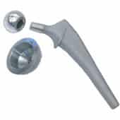
Femoral stem and ball
socket shown above.
Taper specifications
Taper designs may be specified by an included angle and an angularity tolerance; or the slope may be defined as “Basic” and a “form or contour” tolerance applied to the profile. In either case a datum controlling the size of the taper must be located at some point on the taper. Referred to as a “Reference or Datum diameter”, this dimension relates the taper to some feature on the workpiece, such as an adjacent shoulder or a theoretical sharp corner at one end of the taper.
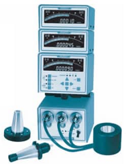
Readout selection
Tapers specified with angularity tolerances require readouts the utilize “A-B” and “A-C” calculation functions to display angularity deviations. Tapers utilizing contour tolerances require direct coupled readouts that display the profile tolerance limits at each set of sensors. Micro IIi Readouts can be conifigured to check either angular deviations or contour toleranced tapers. See table of order codes for taper gages at right.
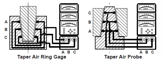
Two or Three air circuits
Taper gages that incorporate three air circuits allow the user to determine if hourglass or barrel shapes are super imposed on taper profiles. They are preferred on long tapers where this profiling error is most common; however space limitations often prohibit including the third circuits on short tapers.
Micro IIi Readouts for Tapers
Model numbers & Applications
Readout for taper seating applications only:
AEQ-42-12M Dual circuit with single (A-B) display. (Available as a single mastered readout only.)
Readouts for taper or shoulder seating applications:
AEQ-42-22M Dual circuit with (A) & (A-B) displays.
AEQ-42-32N Dual circuit with (A), (B) & (A-B) displays.
AEQ-42-33M Triple circuit with (A), (A-B) & (A-C) displays.
Readouts for applications with a contour tolerance controlling the “basic” taper profile:
AEQ-42- 22 Dual circuit with (A) & (B) displays.
AEQ-42- 33 Triple circuit, with (A), (B)& (C) displays.
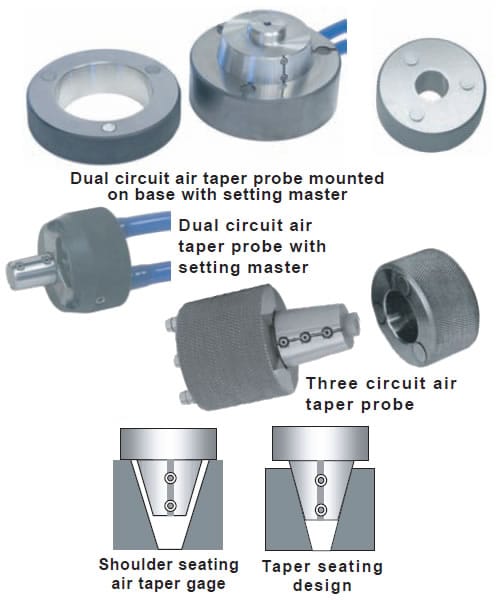 Shoulder seating vs Taper seating gages
Taper gages can be designed to seat on the feature that the taper is referenced to, such as an adjacent shoulder, or they may be allowed to seat on the tapered surface itself — see illustration at right. The shoulder seating design allows measurement of a reference datum diameter on the taper as well as angular deviation. This design is preferred where the tolerance on the reference datum diameter is closely held. For applications where a reference diameter is not closely held, a taper seating design is preferred in order to avoid excessive clearance. HSK machine tool tapers and most medical implant tapers are designed to shoulder seat, while nonflange seating American Steep Machine tool holders and many shaft end tapers are design to taper seat.
HSK Shoulder Seating Taper
per I.S.O. 12164-1
| (inch / mm) | ||||
| No. |
Dia. A |
Dia. B | Dim. L1 |
Dim. L2 |
| 40 | 1.575 40 |
1.1814 30.007 |
.7874 20 |
.1575 4.0 |
| 50 | 1.968 50 |
1.4964 38.009 |
.9843 25 |
.1968 5.0 |
| 63 | 2.480 63 |
1.8902 48.010 |
1.2598 32 |
.2480 6.3 |
| 80 | 3.150 80 |
2.3663 60.012 |
1.5748 40 |
.3150 8.0 |
| 100 | 3.937 100 |
2.9533 75.013 |
1.9685 50 |
.3937 10.0 |
| Above data are provided for product identification — see I.S.O. spec and factory gage drawing for complete specifications. |
||||
Machine Tool Holder Steep Tapers
per A.N.S.I. B5.10
| Above data are provided for product identification — see ANSI spec and factory gage drawing for complete specifications. |
|
|||||||||||||||||||||