
Single master vs Dual master systems
Accurate dimensional measurement requires readouts and gaging members that are calibrated with known standards. Both single and dual master methods of calibration are widely used for air gage systems. The selection of one over the other involves trading off the flexibility and accuracy of the dual master system versus the ease of set up and economy using the single master system. Properly applied, both systems provide acceptable levels of accuracy.
The dual master system user calibrates the readout by observing that the span displayed by the readout corresponds to the span between the minimum and maximum setting masters. This method sets the combined sensitivity of all the components of the gaging system at one time. The sensitivities of components such as flow restrictors, amplifiers, pressure indicators and gaging nozzles, as well as pressure drops in air lines, are included in one overall calibration; thus stringent control of individual components is not necessary to obtain accurate overall results using a dual master system.
The single master system requires controlling the sensitivities of both the gage readout and the air gage member at the factory prior to shipment. The sensitivity of the air gage readout is verified using master orifices that simulate air flow to the gage nozzles; and the gaging member sensitivity is controlled by precise finishing of the gaging nozzles with verification using factory setting masters. Ease of set up is the principal advantage of readouts configured for single master operation, though significant cost savings may be obtained also in large gage sizes by eliminating the cost of a second master.
Single master system accuracy. An allowance must be made for possible scaling errors in both the readout and the gaging member of the single master system. The effect of scaling error increases in direct proportion to the span between the master and the point of measurement. For instance, if a measurement is made .0002″ from the mastered dimension, a scale factor error of 5% would cause an error of 5% of the .0002″ span or .000010″; if the span were extended to .001″, this error would become .000050″. An error allowance of 5% is a reasonable assumption considering that inaccuracies of manufacture and stability with age must be allowed for in both the gaging member and the readout. For most applications, this is an acceptable level of accuracy. Users should be aware, however, that the use of a master that is well outside of the tolerance zone may lead to unacceptable errors in some applications.
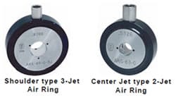
Air Ring Gages
Air Ring Styles – Center-jet style air rings have gaging nozzles near the center of the body. Shoulder-jet style have jets near the leading edge of the bore. For both air rings and air probes, the best wear life is obtained by using thru-hole or center-jet styles when the application permits.
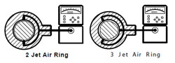
2 & 3 Jet Air Rings – Air ring gages are often made with more than two interconnected air nozzles. Three-jet air rings are commonly specified when centerless ground parts are to be inspected. They will detect three lobe out-of-round conditions prevalent in centerless ground parts that are not detectable with two-point gaging methods (see illustration below). Adding additional jets provides direct display of average diameters.
Air C-Gages
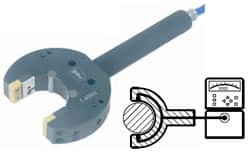
Air C-Gages provide side access making them a convenient means to measure shaft O.D.’s while the workpiece is mounted on a grinder. Western’s C-Gages feature carbide back stops and Kevlar reinforced nylon bumpers that prevent marking parts.
See pages 22 & 23 for specifications and order codes for Air Ring Gage, C-Gages & Accessories