Page 16
Air Probes for Checking Internal Diameters
Air probes are also referred to as air plug gages or air spindles by some manufacturers.
Air probes are also referred to as air plug gages or air spindles by some manufacturers.
Air probes with body diameters from .044″(1.1 mm) to 6.26″(160 mm) are supplied from Western’s stock of semifinished gages. Review the selection criteria on this page and see pages 18 & 20 for dimensional data.
AIR PROBE STYLES
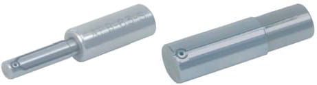
Blind style Air Probes have the sensing nozzles near the front end.
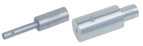
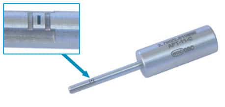
Thru-hole style Air Probes with the sensing nozzle set back from the end which provides maximum wear life.
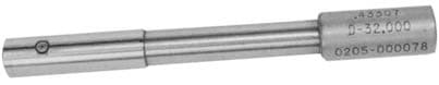
Small Air Probes may require an extension added at the factory to reach into deep holes.
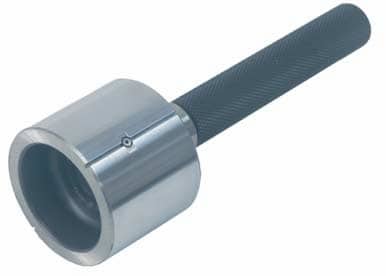
Tubular handles are standard on large series Series 60 to 80 Air Probes (single master types) Above 2.510″.
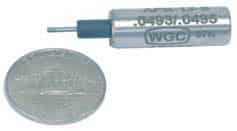
Miniature air probes work well on closely toleranced holes. They are available as dual master types only.
Custom Air Gages with Slot Jets can inspect smaller features than those inspected with round jets. 2.78 mm diameter air probe with .30 mm wide slot is shown above.
AIR PROBE FEATURES
The illustration below shows the construction of a typical air probe. The probe comprises a hardened steel body in which air passages are drilled to two or more gaging nozzles. The body is precision ground to slip into the bore at the low limit of the product tolerance; note the nozzle tips are recessed a small amount below the probe body as shown in the magnified view of the air gage nozzle.
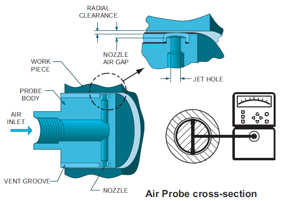
By recessing the air nozzles below the probe body, the measurement is made non-contact so that wear does not directly affect the accuracy of the gage. The air flow purges the gaging surface of contaminants thus making air gage measurements highly repeatable. The probes opposed nozzle design creates a “differential” type of measurement that is independent of how the probe is positioned radially within the test bore — i.e. radial movement causing an increase in air flow in one nozzle is offset by a corresponding decrease in flow in the opposing nozzle. These features are key factors in attaining fast-accurate gaging with unskilled operators.
Application considerations — When selecting an air probe, the jet locations should be checked, bearing in mind that the measurement occurs where the air exits the gaging nozzle. The air jet must be completely covered by the workpiece plus some additional margin — consider a land width that’s twice the jet hole diameter to be about the minimum required for satisfactory gaging. Also note that the probe will not measure closer to the hole bottom than the leading edge of the jet hole. Specifying a super blind style will allow measurement closer to the bottom; but be aware that the nose end of the probe wears more rapidly than the rest of the body so the best gage life is obtained with thru-hole style probes.