Previous Page Previous Page Western Gage Buyers Guide Index Next Page Next Page

PRODUCTION GAGING SOLUTIONS - Flatness & Thickness Gages

FLATNESS AIR GAGE

THICKNESS GAGE


THICKNESS PROBE

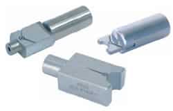
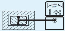
Air Thickness Probes
provide a rapid way to check slot widths, distance between valve spool lands.

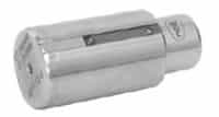
Leaf Jet Air Probes check bores with rough surface finishes or narrow lands too narrow for gaging with open jets.


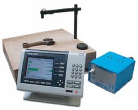
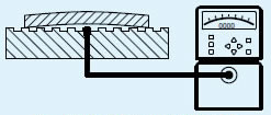
Flatness Gage has air jet incorporated in granite surface plate. Sizes available from 12" to 36" square. Optional overhead laser pointer spots gaging nozzle location when test piece is in place.

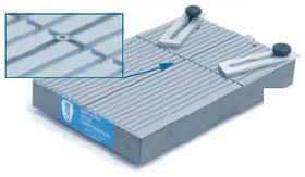
Air Flatness Gage incorporated in tool steel reference flat. Detail view shows air jet imbedded in serrated flat.

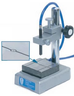
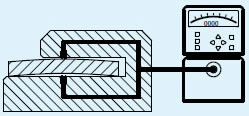
Adjustable Air Thickness Gage Detail view shows the lower air jet. Models with larger anvils are available.

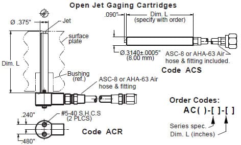
Open Jet Gaging Cartridges are used with Flatness and Thickness gages and similar applications. (See illustrations below). Model ACR has right angle hose connection and mounting screws for installation in surface plates. (Requires drilling the plate and installing a bushing). Model ACS is used on thickness gages and similar applications.

Spherical Air Probes measure female spherical sockets. Applications include hydraulic motor swash plate pads, I.C. engine push rods and medical implants. Fig. A

Spherical I.D. Air Gage checks internal spherical radius in axle differential casting. Fig. B

Orifice flow testing using Micro II Readouts provides an efficient means of controlling the quality of small orifices. Applications include natural gas burner orifices, pesticide sprayer nozzles, and fuel systems components. Test fixture with orifice shown at right. Fig.C

Inspection fixtures incorporating pairs of staggered air jets are a rapid means of checking bore to face runouts. Inspection times of 10 to 20 seconds per part are typical. Use the Micro II's or Gage Chek's "TIR" recording function to facilitate data capture and evaluation. (Note that using this inspection method, the Total Indicated Readings obtained are twice the perpendicularity tolerance as defined in the ASME/ANSI Y14.5M specification). Fig.D

Bore to bore runouts utilizing secondary datums can be inspected using fixtures as illustrated in figure E.

Bore to bore runouts without secondary datums can be inspected if one of the diameters is of adequate length -- see Fig.F.

Perpendicularity, Concentricity, and True position callouts may require additional air nozzles, air circuits and multiple input readouts to prevent "out-of-round" conditions from influencing the gage readings. Consult Western Gage engineering for application feasibility.


Connecting Rod Bend & Twist Gage checks parallelism and center distance between piston end and crank end bores. Inspection system includes custom gaging fixture, quad AEK air-electric converter, and Gage-Chek Readout.

Three Spindle Inspection station checks bore size, O.D. size, I.D. to O.D. concentricity, and bore to face perpendicularity on machined bearing housing. Uses 3 quad AEK air/electric converters coupled to CWK-2 computer.

Twin Spindle Inspection Station. Stepper motor driven slide moves a pair of air probes to measure internal diameters at six locations in an hydraulic valve body. Parts are inspected two at a time with cycle time of 25 seconds. (Image at right)