
Gage accuracy can be no better than the precision of the standards used for calibration.
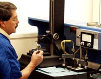
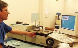 Western’s master gages are fabricated from heat treated and stabilized chrome alloy steel blanks conforming to American Gage Design standard A.N.S.I. B47.1. After heat treat and stabilization cycles, these gages are custom finished by grinding and lapping to the precise dimensions specified. Final calibration is done in a temperature controlled gage calibration lab using electronic comparator instruments and laboratory grade reference standards.
 Gaging accuracy. Good quality control practice calls for specification of masters with tolerances less than 10% of the workpiece tolerances (5% is considered ideal); and for periodic recalibration of the gage. Recalibration intervals are up to the user to establish depending on amount of usage, the accuracies required, and the calibration history of the gage. One year intervals are generally recommended as a starting point for moderate usages.
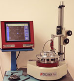 Inspection reports. Western Gage is accredited in accordance with the recognized International Standard ISO/IEC 17025:2005. This accreditation demonstrates technical competence for a defined scope and the operation of a laboratory quality management system (refer to the joint ISO-ILAC-IAF Communique dated January 2009). Western Gage’s calibration system conforms to ANSI/NCSL Z540-1-1994.. Long form Certificates of Calibration are supplied with all master gages.
Setting Master Dimensional Data
See page 27 for order codes
| Ring Gage Masters | ||||
| Diameter A above -incl. |
Dia. C |
Dim. B |
Gage Blank # |
Figure |
| .040 – .060 .060 – .070 .070 – .230 .230 – .365 .365 – .510 .510 – .825 .825 -1.135 1.135 -1.510 |
.94 .94 .94 1.13 1.38 1.75 2.13 2.50 |
.19 .25 .37 .56 .75 .94 1.13 1.31 |
00** sp** 0** 1 2 3 4 5 |
A A A A A A A A |
| 1.510 – 2.010 2.010 – 2.510 2.510 – 3.010 3.010 – 3.510 3.510 – 4.010 |
4.00 4.50 5.00 5.50 6.38 |
1.50 1.50 1.50 1.50 1.50 |
6 7 8 9 10 |
B B B B B |
| 4.010 – 4.760 4.760 – 5.510 5.510 – 6.260 6.260 – 7.010 7.010 – 7.760 7.760 – 8.510 8.510 – 9.100 |
7.25 8.25 9.25 10.30 11.30 12.30 13.30 |
1.50 1.50 1.50 1.50 1.50 1.50 1.50 |
11 12 13 14 15 16 17 |
B B B B B B B |
| ** In these sizes, Western provides a blank that is thicker than the A.N.S.I. standard for more reliable gage mastering. | ||||
| AMERICAN GAGE DESIGN TOLERANCES | |||||
| Size above-incl. inch / mm |
Tolerance – inch / µm | ||||
| XXX | XX | X | Y | Z | |
| .029 – .825 .74 – 20.96 |
.00001 .25 |
.00002 .51 |
.00004 1.02 |
.00007 1.78 |
.00010 2.54 |
| .825 – 1.510 20.96 – 38.35 |
.000015 .38 |
.00003 .76 |
.00006 1.52 |
.00009 2.29 |
.00012 3.05 |
| 1.510 – 2.510 38.35 – 63.75 |
.00002 .51 |
.00004 1.02 |
.00008 2.03 |
.00012 3.05 |
.00016 4.06 |
| 2.510 – 4.510 63.75 – 114.55 |
.000025 .64 |
.00005 1.27 |
.00010 2.54 |
.00015 3.81 |
.0002 5.08 |
| 4.510 – 6.510 114.55 – 163.35 |
.000033 .83 |
.000065 1.65 |
.00013 3.30 |
.00019 4.83 |
.00025 6.35 |
| 6.510 – 9.010 163.35 – 228.85 |
.00004 1.02 |
.00008 2.03 |
.00016 4.06 |
.00024 6.10 |
.00032 8.13 |
| Set Disc Masters | ||
| Diameter A above -incl. |
Dim B |
Gage Style |
| .150 – .230 .230 – .365 .365 – .510 .510 – .825 .825 – 1.135 1.135 – 1.510 1.510 – 2.510 2.510 – 8.010 |
1.19″ 1.31″ 1.44″ 1.56″ 1.69″ 1.94″ .88″ 1.00″ |
1 1 1 1 1 1 3 3 |
| Master Setting Plugs | ||
| Diameter A above -incl. |
Dim B |
Gage Style |
| .060 – .825 .825 – .947 .947 – 1.135 1.135 – 1.510 1.510 – 2.010 2.010 – 3.510 3.510 – 8.010 |
2.00″ 1.25″ 1.37″ 1.50″ .88″ 1.00″ 1.00″ |
Reversible Trilock Trilock Trilock Trilock Trilock Trilock |
Bilateral / Unilateral Tolerances
A.G.D. classes define the total tolerance zone for the gage. Master gages are made with the A.G.D. class tolerance split equally (bilaterally). Go and NoGo fixed limit gages for functional testing of workpieces are normally unilaterally toleranced into the tolerance zone of the part. Thus, “Go Rings” and “No-Go Plug” gages are unilaterally minus toleranced. “No-Go Rings” and “Go Plug” gages are unilaterally plus toleranced. For example, a .5000″ master ring gage, with a class “XX” tolerance (.00002″) is finished to a diametrical tolerance of ±.00001″. Ordered as a No-Go ring gage, the .5000″ ring would be finished to +.00002″/.00000″ diametrical tolerance.