AIR PROBES & AIR RINGS
Check List for Air Probes & Air Rings
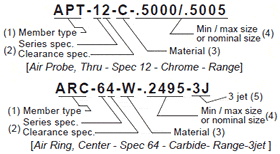
- Gaging member type . . . . . . . . . . . . . . order code
Air Probe, Thru-hole . . . . . . . . . . . . . . . . . . .APT
Air Probe, Blind . . . . . . . . . . . . . . . . . . . . . . .APB
Air Probe, Super blind . . . . . . . . . . . . . . . . . APS
Air Ring, Center jet . . . . . . . . . . . . . . . . . . . . ARC
Air Ring, Shoulder . . . . . . . . . . . . . . . . . . . . .ARS
Air Ring, extra close . . . . . . . . . . . . . . . . . . . ARX - Series specification
Match the gage with the series that includes the Readout it is to be used with. Then complete the gaging member specification by changing the last digit of the series number to show the clearance specification. Pages 18 & 20 show standard clearances for dual and single master systems. - Material . . . . . . . . . . . . . . . . . . . . . . . . order code
Steel . . . . . . . . . . . . . . . . . . . . . . . . . . . . . . S
Chrome . . . . . . . . . . . . . . . . . . . . . . . . . . . C
Carbide . . . . . . . . . . . . . . . . . . . . . . . . . . . W
CPM-10V (Premium wear resistant tool steel) V - Size of the setting master(s).
Gaging members for Series10 – 50 comparators require that both minimum and maximum setting master sizes be specified. Series 60 thru 80 members require only the nominal size. Add suffix “mm” to denote millimeter sizes. - Special requirements — modifications required for the application such as:
Three Jets – add suffix “-3J” to order code.(Two-jet members are furnished unless otherwise specified).Extra length – Extra length is required for small air probes to gage deep holes — add suffix “-XLC” and specify the jet to handle dimension [“C” ]. — see illustration below.
Other specials – for modification to standard blanks not requiring a custom drawing, add suffix “-SP” and specify modification in remarks field. - Special marking
Gaging member sizes are marked on all members. Customer tool numbers will be added upon request. Numbers with more than 10 characters are subject to additional charges.
SETTING MASTERS

Check List for Setting Masters
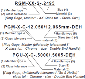
- Specify member type . . . . . . . . . . order codes
Ring Gage, Master . . . . . . . . . . . . . . RGM
Ring Gage, Go . . . . . . . . . . . . . . . . . .RGG
Ring Gage, NoGo . . . . . . . . . . . . . . . RGN
Plug Gage, Master . . . . . . . . . . . . . . PGM
Plug Gage, Go . . . . . . . . . . . . . . . . . .PGG
Plug Gage, NoGo . . . . . . . . . . . . . . . PGN
Plug Gage, Go /No Go set . . . . . . . .PGU
Set Disc, (ANSI B4 7.1 style 3) . . . . .SDS
Set Disc, (ANSI B4 7.1 style 1) . . . . .SDL - Specify class tolerance
Select class tolerance Z thru XXX from the table pg -25. Bilaterally toleranced master gages are recommended for air gage applications. - Material . . . . . . . . . . . . . . . . . . order codes
Steel . . . . . . . . . . . . . . . . . . . . . . . . . . S
Chrome . . . . . . . . . . . . . . . . . . . . . . . C
Carbide . . . . . . . . . . . . . . . . . . . . . . . W - Specify size(s) of setting master
Sizes are assumed to be in inches unless followed by “MM”( millimeters). Careful checking of required size prevents expensive mistakes. - Select handle type . . . . . . . (Plug gages only)
Single end handle. . . . . . . . . . . . . . SEH
Double end handle . . . . . . . . . . . . DEH
Member only . . . . . . . . . . . . . . . . . M /O - Specify marking
Size and class tolerance are marked on all master gages. Customer tool numbers up to ten characters will be marked at no charge.


