
 High Precision Dimensional Inspection on Parts with Rough Surfaces Using “Air”
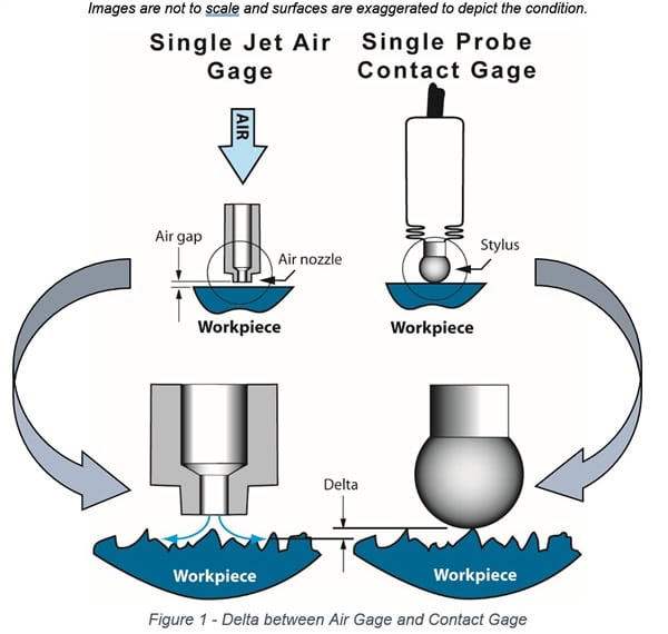
A consideration when using air gaging is how the surface roughness of the workpiece effects the measurement result. An air gage will produce a different value when compared to traditional contact type instruments, such as a touch-probe or stylus, if the workpiece surface finish is not sufficiently smooth. This condition is illustrated in Figure 1. A contact probe on an LVDT for instance will ride on the peaks of the surface. The air jet, exiting the nozzle of an air gage, will not be entirely restricted by the peaks but will find a flow path beyond the peaks and into the valleys of the surface – and as a result indicate somewhere below the peaks.
 The Inspection Problem
When air gaging is used for inspection, operators are sometimes faced with the problem of correlating results with a contact gage due to two common situations:
- air gaging is introduced into a process where traditional contact type gaging is being used, and validation of the new system is required, or
- the manufacturing department or vendor is producing the part and conducting in-process inspection using an air gage, and the QA department is conducting sample inspection of the parts using a CMM.
The goal in these two cases, as in most cases, is correlating the measurement systems.
 Correlating the Air Gage
Recommended practice is to first confirm that the two gages are producing similar results – on a smooth surface. Do this by applying the air gage master (typically a lapped and calibrated plain ring , setting plug or set disc) to both the air gage and the contact gage – assuming the contact gage is set with its own master. If the two gages give similar results without the effect of surface roughness, than it can be assumed that there are no other influences to alter the results and that the gages are both measuring properly.
Now the gages can be used to measure production parts. A small sample of production test parts is adequate. Care must be taken to not introduce any error other than what the surface roughness would produce. This is best achieved by insuring that the two gages are measuring the exact same spot on each part. If this is a diametral measurement for instance, control the location of the nozzles at a fixed height from some reference datum. Also control the angular position around the circumference. An air gage essentially measures the average height of a spot on the surface of the part that is the projected area of the nozzle. This is the area that should be consistently located on the part.
After recording data, the average difference of the two gages should be calculated. This average value is the offset value that will be used to convert the air gage results to an equivalent contact gage measurement.
To confirm the offset value, obtain a surface roughness measurement in terms of Ra or Rz on a sample production part and use the graphs below to confirm that the delta computed from the test parts is in-line with the expected delta from the graphs.
Figure 2 is the graph of data from a study that provides an estimate of the typical delta magnitude that can be expected for a given surface roughness. In this graph the x-axis is the single surface Ra value in micro-inches. The y-axis is the delta between a single sensor air gage and contact gage in micro-inches.
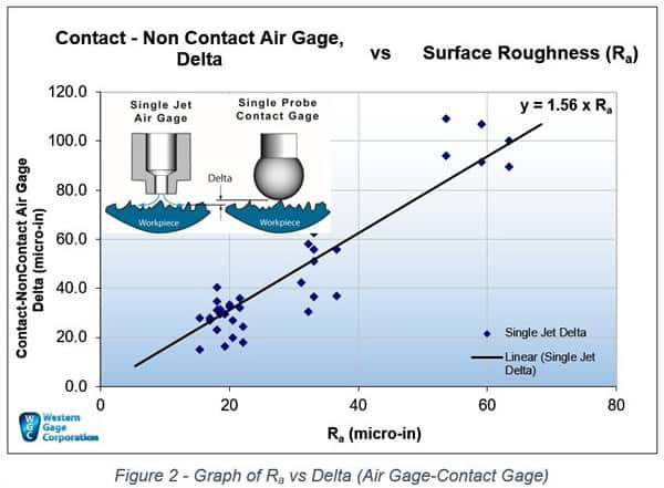
The relationship can be approximated by the equation y=1.56 x Ra, where y is Delta. Note that if a diameter is being measured with dual opposing sensors, the Ra value must be doubled due to the fact that there are two surfaces involved.
On dual sensor ID measurements, an air probe will indicate larger than a contact gage. The opposite is true for dual sensor OD measurements – an air ring will indicate smaller than a contact gage. As an example, on a 2-jet ID air gage (probe) that is measuring parts with a surface roughness of 10 micro-inch Ra, the air gage will read about 31 micro-inches larger than a contact gage.
Figure 3 reflects the Rz measure of roughness. The relationship is y=.31 x Rz. Again y is the Delta.
The conventional wisdom (of unknown origin) is that the contact-to-air gage measurement difference is about half the peak-to-valley height. This implies that on-average the air gage is going to report a point about half way down from the surface.
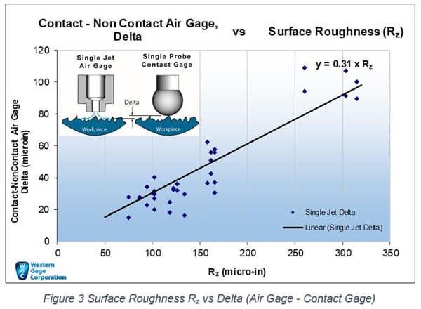
Since Rz is a measure of the average peak-to-valley height, the data from the graph indicates that the delta is not ½ the peak-to-valley height but actually less than 1/3 the height (y=.31 x Rz). The 1/3 estimate may be more realistic than 1/2 for the reason that flow of fluids across a surface will develop a boundary layer at the surface in which little to no flow occurs. So in the deepest valleys of the surface, there will be very restricted flow, shifting the bulk of the flow (and the air gage measurement) closer to the peaks.
While the dispersion of data is not precise, the graphs can be used to confirm test data as described above or used as an estimate of the offset value when air gaging parts with known surface roughness.
Defining the Part Surface
When evaluating surface roughness and the appropriateness of an air gage, decisions depend not only on the magnitude of the surface roughness, but also on the functional requirement of the part. Does defining the parts surface beyond the peaks of the surface roughness best control the end use? For example, if the test part is a spool valve and the primary requirement is to control fluid leakage, sub-surface is probably the best criteria; while for completely free sliding fits between mating cylindrical parts, the max material condition defined by the peaks may be the best definition of the part surface. For fitting ball bearing assemblies where a light press fit is usually allowed, and in many cases desired to eliminate radial play, defining the surface below the peaks may be what’s called for.
Defining the surface, choosing the right air gage, and using the provided graphs will put you on the path toward producing parts that are best suited for your application.